How to Align CNC Drawings and Inspection Plans for Critical Hole Patterns
Before releasing a machined titanium part for production, tie the hole pattern to its assembly function, identify the governing drawing or model, and agree how the supplier will verify that requirement.
Table of Contents
Before releasing a machined titanium part for production, tie the hole pattern to its assembly function, identify the governing drawing or model, and agree how the supplier will verify that requirement. A quick check between hole edges may be useful on the shop floor. Whether it can support acceptance depends on the requirement it measures and the evidence connecting it to the controlled drawing.
Start with the way the part locates in the assembly
Ask the design owner which features locate the part, which face seats against the mating component, and which holes provide clearance. A locating pin and a fastener can serve different functions even when their holes appear in the same pattern. Mark the critical features on an approved view and link them to the part revision. Where the design uses datum features, identify the surfaces or features the inspection team must establish from the product definition.
Consider two round holes whose diameters may vary within their size tolerances. The clear gap between the nearest edges can change while the centres stay fixed. Two parts with the same edge gap can also have different centre spacing if the holes differ in size. An edge check may be suitable for a material gap requirement. To use it for a centre spacing or position decision, quality and engineering need to establish how it relates to the actual callout.
ASME describes Y14.5 as a language for specifying and interpreting geometric dimensioning and tolerancing (GD&T) on drawings and digital product definitions. Confirm which standard and edition the order invokes before interpreting a position callout, datum reference or modifier. ASME Y14.5 scope
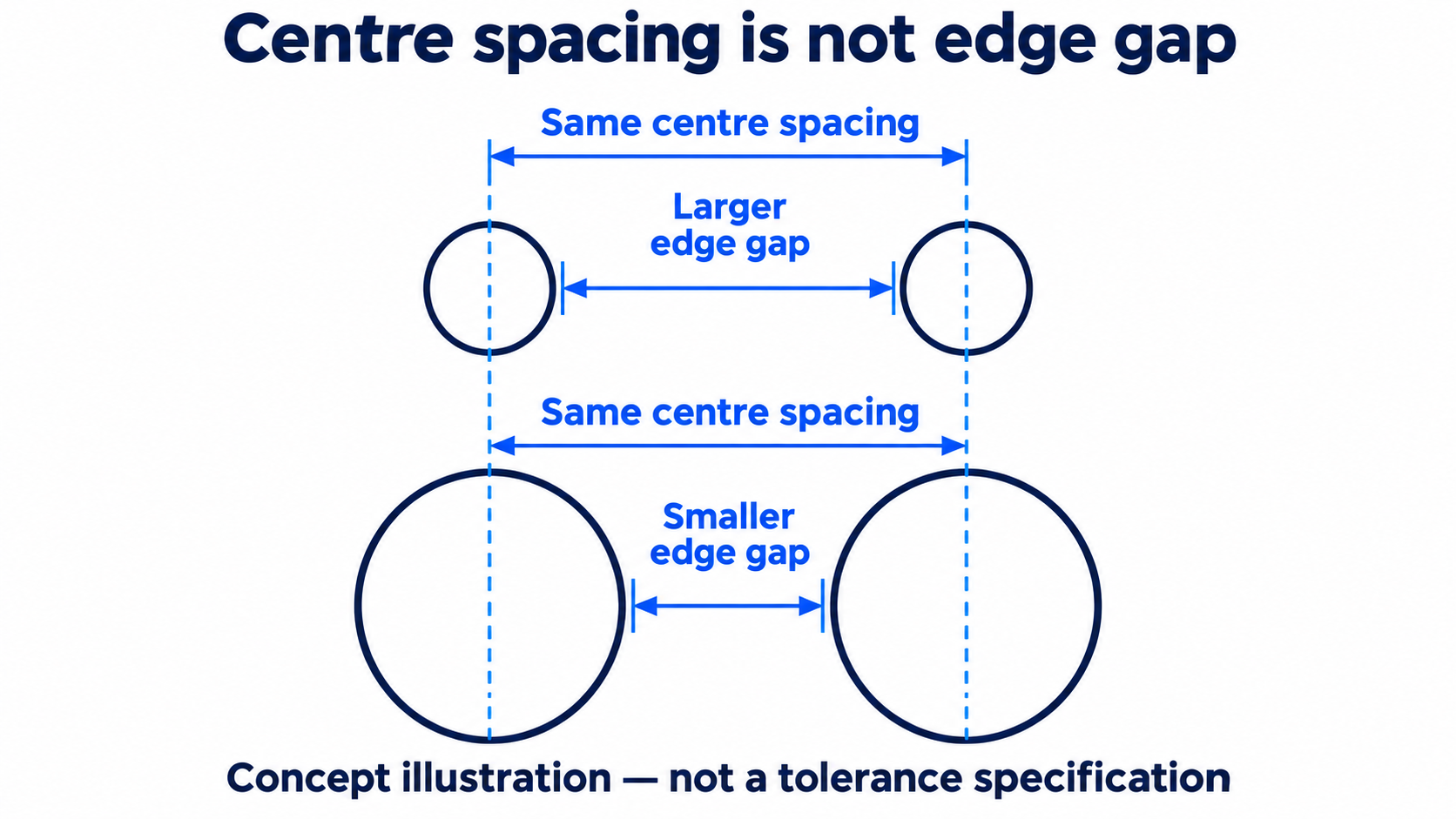
Two pairs of holes share the same centre spacing but have different edge gaps because their diameters differ. Concept illustration showing why edge gap and centre spacing describe different characteristics; it does not specify a tolerance.
Carry the drawing requirement into the inspection plan
Give each critical characteristic an identifier. For each one, record its drawing location, controlling requirement, measurement method and the evidence that will appear in the report. If a shop creates a helper sketch for setup, link it to the drawing revision and label any derived dimensions by purpose. A shop target can help an operator detect drift. The acceptance decision still follows the approved product definition and any authorized deviations.
Decide what result the buyer needs. A documented coordinate measuring machine (CMM) program may suit a request for measured feature locations. A functional gauge may suit a defined pass or fail check when its design and scope have been agreed. Ask the inspection team to explain how the chosen method establishes the required reference, captures the feature and resolves results near the acceptance limit. The appropriate method depends on the geometry, tolerance and decision.
Resolve a disagreement before releasing the parts
If two reports disagree, compare the characteristic ID, part or lot identity, revision, reference alignment, setup and evaluation settings before comparing the numbers. The inspectors may be measuring different characteristics, such as a gap on one side and a position relative to specified datum features. Where the methods still disagree on the same requirement, agree on a comparison using identified parts and ask the responsible quality team to document how it resolved the result.
A change to the acceptance condition needs authorization from the party designated by the order. For example, if a fixture limits access to a hole, record the limitation and ask whether to change the method, add a verification step or seek a formal drawing clarification. Include the disposition with the release record so the same decision can be explained on a repeat order.
For a drawing review, send an approved view of the mating interface, the governing revision and the characteristic list. Include any inspection results you want the supplier to reproduce, with the method and report format. HELE titanium machining enquiries
Frequently asked questions
Which document controls if the model and drawing disagree?
Check the document precedence defined by the order. If it does not resolve the discrepancy, ask the buyer's design authority for a documented clarification before using either value for acceptance.
Can a derived edge dimension appear on a shop sketch?
Yes. Identify the source feature and revision and say whether the derived value is for setup, process monitoring or an approved verification method. Any change to the specified acceptance basis requires authorization.
Can a mating part be used for an assembly check?
It can answer whether those particular parts assemble under the agreed conditions. If the order requires interchangeability or a specific geometric characteristic, keep verifying it by the agreed method.
What should a CMM report identify besides a measured value?
Agree which characteristic and part identifiers, measurement alignment and program revision the reviewer needs. For a disputed result, those details help the two inspection teams reconstruct how the reported value was obtained.
Does a current calibration record settle a borderline result?
It tells the reviewer about the instrument's calibration status. The inspection team still needs to assess whether the setup and method can support the decision and follow the agreed rule for results near the limit.
What if the hole pattern passes but a hole diameter fails?
Record both outcomes. A pass on the pattern does not dispose of a separate size requirement. Obtain the required correction or authorized disposition before releasing the affected parts.
Prepare a technical enquiry
Share the product form, grade or standard, dimensions, quantity and inspection requirements.
Ask a technical question →References

About the publisher
HELE Titanium
HELE Titanium supports industrial buyers with titanium materials, electrochemical anodes and PEM system project review.